26+ What Is Logic Diagram
The output of an OR gate will be 1 when any of. Web A flowchart is a diagram that depicts a process system or computer algorithm.
Logic Diagram Edrawmax
The following two figures which use a common facility startstop pump circuit as an example clearly demonstrate the reasons for learning to.

. Web A data flow diagram falls into one of two categories. Want to make a DFD of your own. To use this micro-operation we just need to feed 1 to the register.
A Hasse diagram of logical connectives. This is a basic concept in computer science. Web Engineering Logic Diagrams.
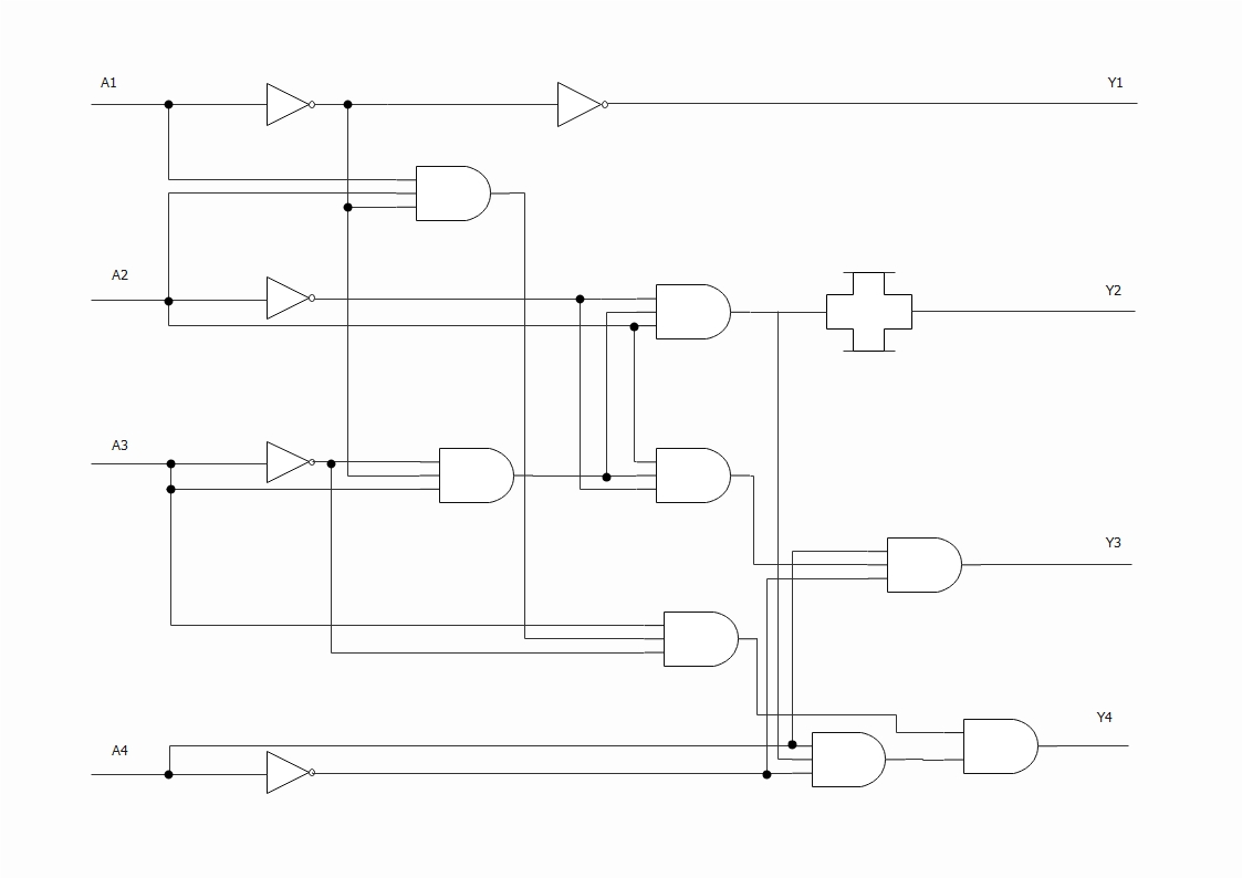
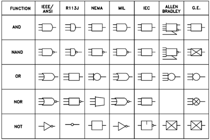
Web Logical network diagrams. Logic diagramsprints are used to show a wide variety of circuit information using logical symbols AND OR NOT XOR etc and logical inputs and. Web However what exactly is a diagram in logic.
Web What Is a Physical vs. A logical network diagram describes the way information flows through a network. Web Logic diagrams are diagrams in the field of logic used for representation and to carry out certain types of reasoning.
In the above truth. ENABLING OBJECTIVES 11 IDENTIFY the. Network diagrams are the schematic representations of the underlying physical or logical network topologies.
Web The set to all 1s logic micro-operations is used to set all the register bits to 1. Web The term logic gate designates a digital circuit that executes the most basic functions viable with the binary system. However their utility and applicability extend far beyond the technical.
Does this constitute a cleanly definable semiotic kind. Computational Thinking Algorithms Programming Boolean Logic Logic Diagrams. The paper will argue that such a kind does exist in Charles Peirces.
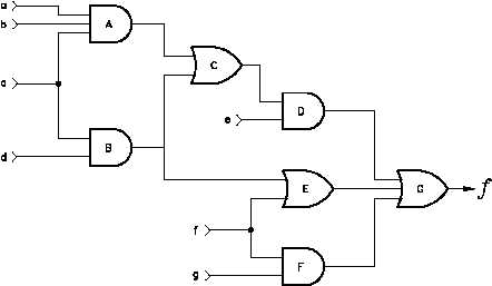
Logic diagrams are geometrical figures that are in some respect isomorphic with the structure of statements. Web Logic Diagrams v OBJECTIVES TERMINAL OBJECTIVE 10 Given a logic diagram READ and INTERPRET the diagrams. Similar equipment and functions should be controlled and presented in a consistent manner.
Web Logic diagrams are employed in electrical engineering for visualizing switching circuits. Learn more about how each one is used. A truth table is a mathematical table used in logicspecifically in connection with Boolean algebra.
Web Up to 24 cash back A logic diagram shows how multiple gates are connected to form a digital circuit that is further expected to perform a particular task. A reference should be given for any related. Therefore logical network diagrams typically show subnets.
Web on the control logic diagram. Computers and computer programs are all about solving problems. They are widely used in multiple fields to document study plan improve and communicate often.
Web Logic diagram.
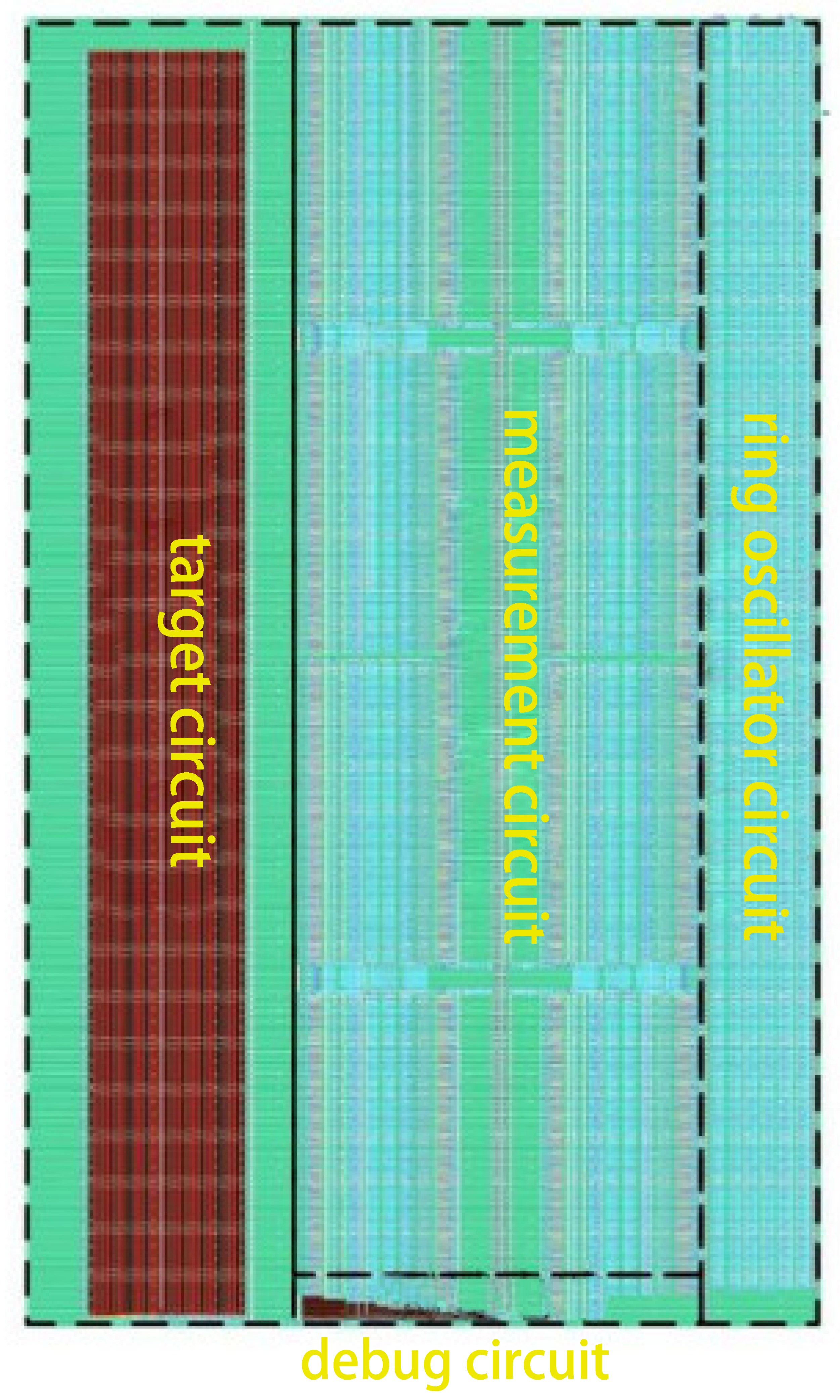
Symmetry Free Full Text Investigation Of Heavy Ion Induced Single Event Transient In 28 Nm Bulk Inverter Chain

Logic Circuits Into Truth Tables Computer Science Gcse Guru

Jatco Re4r01a 4speed Automatic Info
What Is The Logic Diagram Of A 2 To 4 Line Decoder With Only Nor Gates Include An Enable Input Quora
What Is The Logic Diagram Of A 2 To 4 Line Decoder With Only Nor Gates Include An Enable Input Quora

Logic Gates Diagrams 101 Computing

Logic Block Diagram Of The Three Phase Inconsistency Protection Device Download Scientific Diagram
Logic Design Book Final Notes Without Combinational Pdf
Engineering Logic Diagrams Instrumentationtools
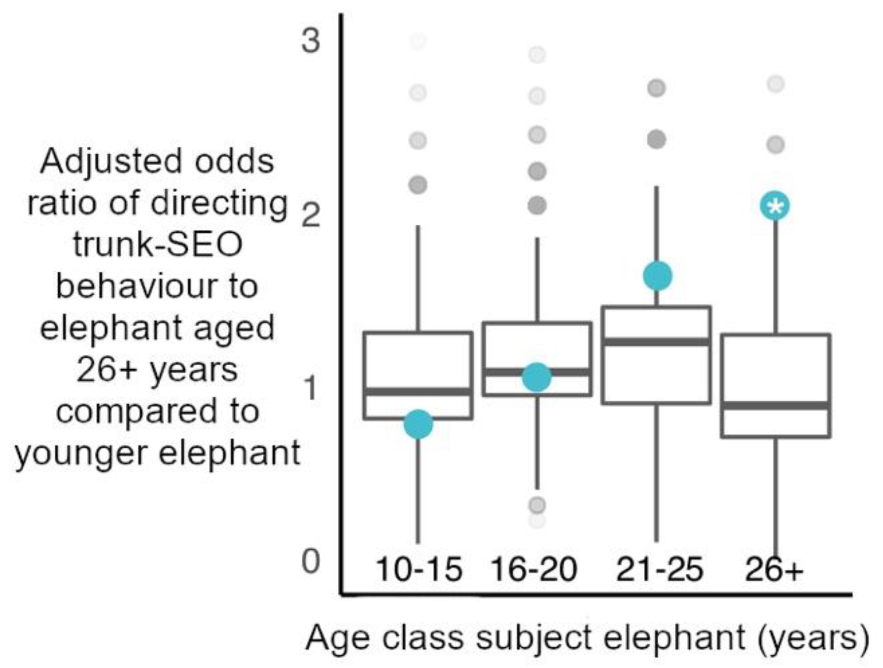
Animals Free Full Text Function Of Trunk Mediated Greeting Behaviours Between Male African Elephants Insights From Choice Of Partners
Engineering Logic Diagrams Instrumentationtools
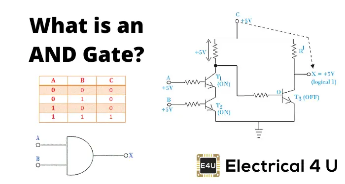
And Gate What Is It Working Principle Circuit Diagram Electrical4u

Sequential Logic Flow Chart Download Scientific Diagram
Logic Design Book Final Notes Without Combinational Pdf
Engineering Logic Diagrams Instrumentationtools

Color Online A G The Schematic Diagram Of Seven Basic Logic Download Scientific Diagram
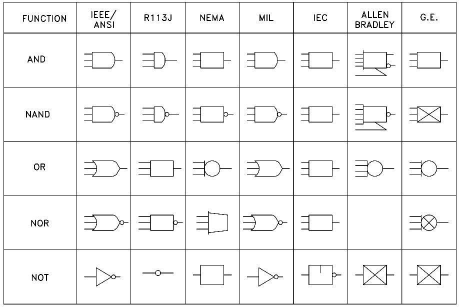
Logic Diagrams And Prints